So this idea had been percolating for a while of building a 24/7 boat monitoring device based on a Raspberry Pi.
I wanted it to be solar, so that it could be on all the time (where we keep our boat docked, we can’t be on shore power unattended — it’s a fire hazard and a huge risk).
On Pi Day (3/14) of this year, ZipCar held a giveaway — tweet your Pi Zero ideas, and if they like your idea, they’ll send you one. They gave away 314 of them. My idea was one of the winners.
While waiting for my free Pi Zero Wireless, I built an interim solution as a proof of concept, using a Pi 3 and a Harbor Freight 45W solar kit.
I strapped the solar panels (mounted inconveniently to a PVC-style frame) to a convenient spot on the deck of the boat, wired it to the charge controller in the main salon, and then to the head battery just below.
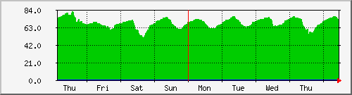
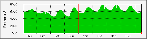
I picked a humidity and temperature sensor (the DHT-11) and installed it on a small breadboard and connected it to pins on the Pi 3. I wrote an app to query it every five minutes and graph the results with MRTG.
It has been running for about two weeks now, purely off of the solar and battery. So the system seems to be working.
Once the Pi Zero Wireless arrives, and I solder the 40-pin header onto the board, I plan to have it take the place of the Pi 3. The Zero uses significantly less power.
I may also add at some point a circuit to monitor solar charge and battery life, and graph that info.
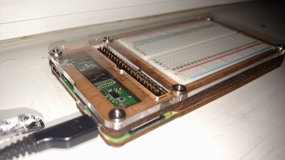
C4 Labs has a brilliant Pi Zero wood and acrylic case that shows off and protects the Pi in a very classy way, matches the decor of the boat’s interior, and includes a built-in breadboard!

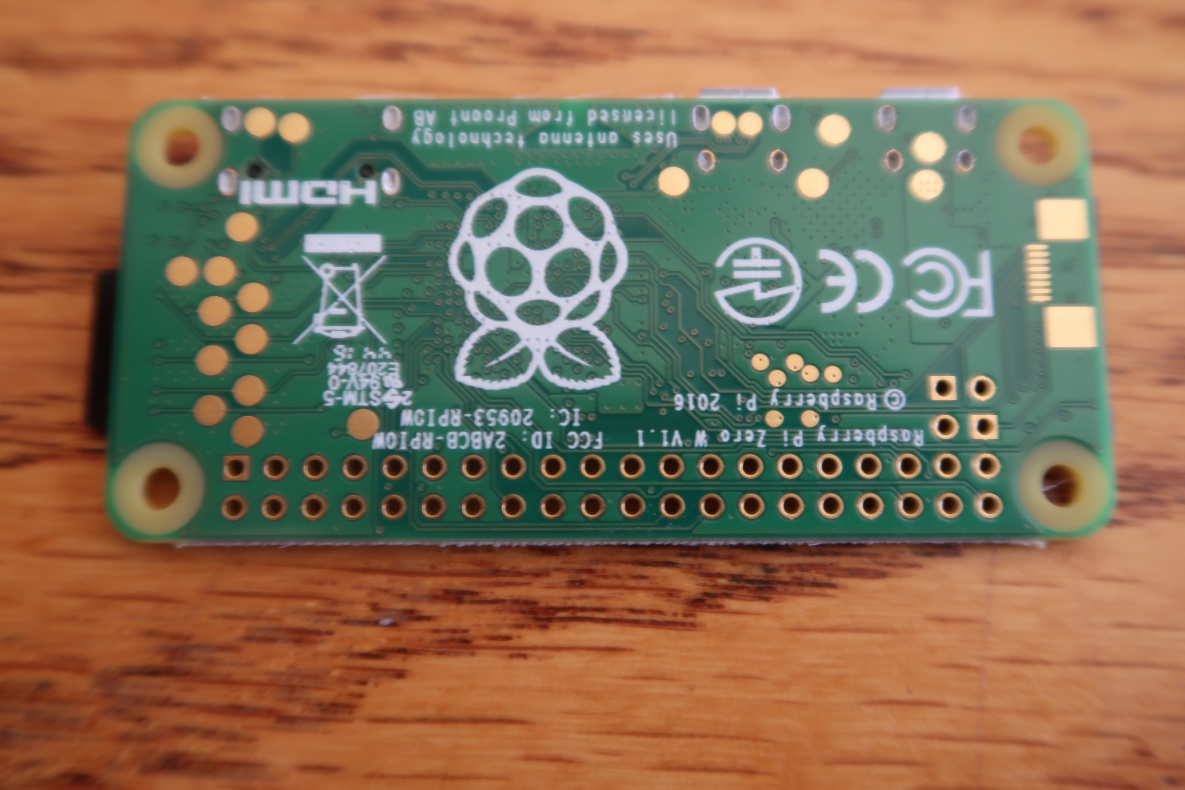
So here is the Pi Zero W before soldering the header pins.
And here it is with the pins installed, but prior to soldering.
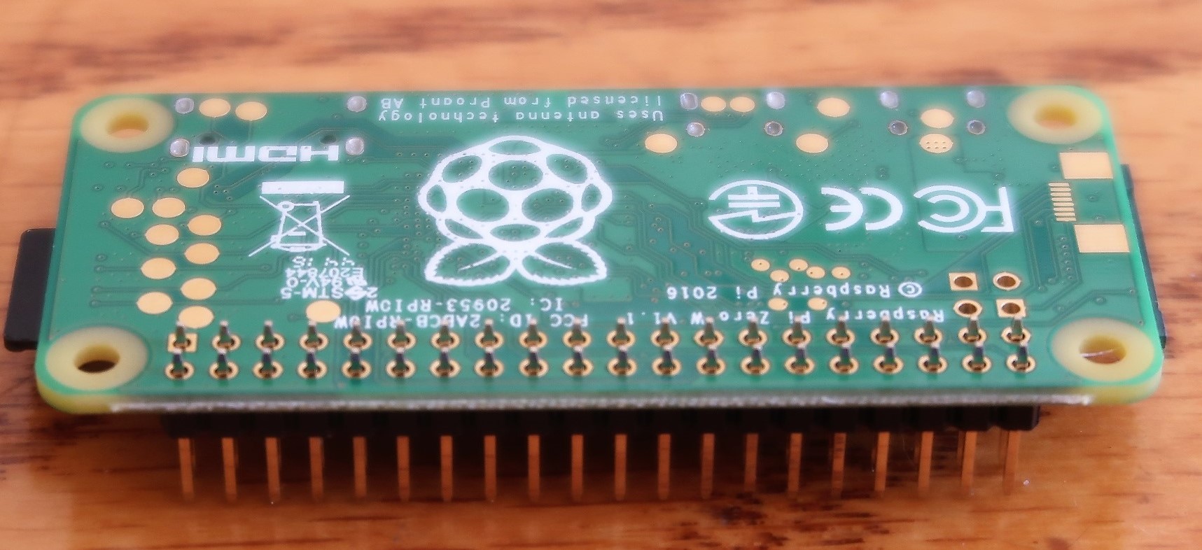
Last but not least, here’s my mediocre soldering job. 🙂 To my credit, it’s the first time I’ve soldered at this level. I think I did… “not too badly.”

Anyhow, you can see why I was reluctant to embark on a solder-based solution to the SR-16 bending project.
I determined that a couple of pins were bridged, and clearly a couple of them could use a redo, but I tested them, and only three pins aren’t functioning as expected (either bridged to power or bridged to ground). I’ll fix it later. Meanwhile, it’s good enough for my project.
I hope to upload more photos of the final product once it’s installed.